11 years ago cheap, LEDs, Uncategorized, vegetables

While my existing system was working I decided to make an upgrade to the electronics on my old grow box controller specifically to have a much more industrial strength version that will run without problems for decades to come. This version also is much safer…still probably not quite to a building code but much less worries to burning my garage down in the middle of the night. Finally it is modular if there are problems in the future I can easily switch out electronics or sensors.
Well now I have attempted to justify my reasons this is what I used to put the whole thing together:
Parts List
If we had lawyers, they probably would want us to say this:
WARNING: I am not an electrician and do not pretend to be one. I do not know the specific building electrical codes of your area, so please be sure your wiring is completed under the proper safety code for your area. As always, using high voltage electricity can result in self-electrocution or burn down your house if not done safely so if you are not comfortable doing this wiring please contact a qualified professional.
Putting it all together
On the electronics side overall the circuits are actually pretty simple and if using a breadboard definitely something that could be tackled by a beginner. Though on the other side since this project is dealing with AC current I definitely would recommend caution (no hands unless power is unplugged) or have someone a little more comfortable with 120/220V help you out.
The Brains
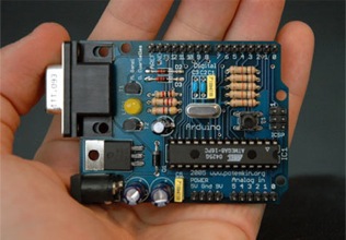
I will be the first to admit that using an Arduino for this application is complete overkill for this application but it gives plenty of room for additions in the future. For all intents and purpose you could have your grow box completely controlled from the Arduino own processing power though on my case the software and UI is more interesting part to me. For this reason the Arduino code is actually very “dumb” basically just taking commands via the build in serial through USB and setting digital outputs to HIGH/LOW or reading analog inputs.
Here is the code for your grow box controller:
1: /*
2: * GrowBox Arduino Interface
3: *
4: * Descriptions: Simple interface to digital and analog controls by passing serial inputs
5: * For example:
6: * "A1" to read analog value on pin 1
7: * "D1H" to set digital pin 1 to HIGH
8: */
9: #include <OneWire.h>
10:
11: //1-wire
12: OneWire ds(8); // on pin 8
13: #define BADTEMP -1000
14:
15: //define unique sensor serial code
16: byte temperature[8];
17:
19: #define PIN_VALUE 1 // numeric pin value (0 through 9) for digital output or analog input
18: #define ACTION_TYPE 0 // 'D' for digtal write, 'A' for analog read
20: #define DIGITAL_SET_VALUE 2 // Value to write (only used for digital, ignored for analog)
21:
22: int NUM_OF_ANALOG_READS = 2;
23: char commandString[20];
24:
25: void setup()
26: {
27: Serial.begin(9600);
28:
29: setOneWireHex();
30:
31: // Power control
32: for(int i=0; i<=7; i++)
33: {
34: pinMode(i, OUTPUT); // sets the digital pins as output
35: digitalWrite(i, LOW); // turn everything off
36: }
37: }
38:
39: void loop()
40: {
41: readStringFromSerial();
42:
43: if (commandString[ACTION_TYPE] != 0) {
44: int pinValue = commandString[PIN_VALUE] - '0'; // Convert char to int
45:
46: if(commandString[ACTION_TYPE] == 'A')
47: Serial.println(analogRead(pinValue));
48: else if(commandString[ACTION_TYPE] == 'D') {
49: if(commandString[DIGITAL_SET_VALUE] == 'H')
50: digitalWrite(pinValue, HIGH);
51: else if(commandString[DIGITAL_SET_VALUE] == 'L')
52: digitalWrite(pinValue, LOW);
53:
54: Serial.println("OK");
55: }
56: else if(commandString[ACTION_TYPE] == 'T') {
57: float temp = get_temp(temperature);
58:
59: Serial.print(temp);
60: Serial.println("C");
61: }
62: else if(commandString[ACTION_TYPE] == '1') {
63: printOneWireHex();
64: }
65: else if(commandString[ACTION_TYPE] == 'V') {
66: Serial.println("VERSION_1_0_0_0");
67: }
68: else if(commandString[ACTION_TYPE] == 'P') {
69: Serial.println("PONG");
70: }
71:
72: // Clean Array
73: for (int i=0; i <= 20; i++)
74: commandString[i]=0;
75: }
76:
77: delay(100); // wait a little time
78: }
79:
80:
81: void readStringFromSerial() {
82: int i = 0;
83: if(Serial.available()) {
84: while (Serial.available()) {
85: commandString[i] = Serial.read();
86: i++;
87: }
88: }
89: }
90:
91: void setOneWireHex() {
92: ds.reset_search();
93: ds.search(temperature);
94: }
95:
96: void printOneWireHex() {
97: ds.reset_search();
98: if ( !ds.search(temperature)) {
99: Serial.print("NONE\n");
100: }
101: else {
102: ds.reset_search();
103:
104: int sensor = 0;
105: while(ds.search(temperature))
106: {
107: Serial.print("S");
108: Serial.print(sensor);
109: Serial.print("=");
110: for(int i = 0; i < 8; i++) {
111: Serial.print(temperature[i], HEX);
112: Serial.print(".");
113: }
114: Serial.println();
115: }
116: }
117:
118: ds.reset_search();
119: }
120:
121: float get_temp(byte* addr)
122: {
123: byte present = 0;
124: byte i;
125: byte data[12];
126:
127: ds.reset();
128: ds.select(addr);
129: ds.write(0x44,1); // start conversion, with parasite power on at the end
130:
131: delay(1000); // maybe 750ms is enough, maybe not
132: // we might do a ds.depower() here, but the reset will take care of it.
133:
134: present = ds.reset();
135: ds.select(addr);
136: ds.write(0xBE); // Read Scratchpad
137:
138: for ( i = 0; i < 9; i++) { // we need 9 bytes
139: data[i] = ds.read();
140: }
141:
142: int temp;
143: float ftemp;
144: temp = data[0]; // load all 8 bits of the LSB
145:
146: if (data[1] > 0x80){ // sign bit set, temp is negative
147: temp = !temp + 1; //two's complement adjustment
148: temp = temp * -1; //flip value negative.
149: }
150:
151: //get hi-rez data
152: int cpc;
153: int cr = data[6];
154: cpc = data[7];
155:
156: if (cpc == 0)
157: return BADTEMP;
158:
159: temp = temp >> 1; // Truncate by dropping bit zero for hi-rez forumua
160: ftemp = temp - (float)0.25 + (cpc - cr)/(float)cpc;
161: //end hi-rez data
162: // ftemp = ((ftemp * 9) / 5.0) + 32; //C -> F
163:
164: return ftemp;
165: }
Copy and paste the above code into your Arduino software. For the code above I used the OneHire.h library which is free to use and can be downloaded from here. To be able to use this library simply copy the contents to C:\arduino\hardware\libraries\OneWire. Now you should be able to Compile (CTRL+R) and upload the code to the board (CTRL+U)
Now with the software uploaded you can send some simple serial commands via its built in USB to serial adapter to interact with it. The interface is are broken up into 1 to 4 character commands, which I will detail below
| Command |
Description |
| T |
Returns temperature from One Wire component |
| D4H |
Sets digital pin 4 to HIGH (ON) (replace 4 for alternate pin) |
| D4L |
Sets digital pin 4 to LOW (OFF) (replace 4 for alternate pin) |
| A1 |
Reads analog value from pin 1 (replace 1 for alternate pin) |
| PING |
Returns PONG which is used to confirmed controller is online |
| V |
Returns version which is some forethought into the PC application being able to support different versions of controller software |
Using the build in serial monitor tool in Arduino.exe, my application, or you should be able to control your Arduino with this very simple command based interface
Now you can hook up some LEDs and watch them blink which is fun for a little while but if you want to add some grow box components read on….
Temperature Sensor
As you can see I have fully embraced the circuit schema on the back of a napkin idea. These are the actual diagrams I crumpled up and stuffed in my pocket with several trips to the garage for some final soldering of various joints until everything was solid.
Below is the simple circuit required to get your 1Wire temperature sensor working. I would recommend checking your documentation (if not labels on the chip) for the orientation to have 1 and 3 correct, if you have it wrong you should get some complete unrealistic number. Hook ground up to pin1 on the DS18S20 and pin 2 hooked up to the digital input pin 8 on the Arduino with 5V with a 4.7K resister in between to step down the voltage.
If everything is hooked up correctly you should get the current room temperature in Celsius by sending command “T” to your Arduino. If you prefer Fahrenheit uncomment line 162 and recompile and upload your changes, though if using my software I support both degree types and do the conversion in the the software. To make sure everything working (or just to play with your new toy) put your fingers on the chip for a couple seconds and take another measurement unless you keep your house very warm the temperature should go up a couple of degrees

Turning things on and off (Relays)
If you were smart enough to check the current requirements of your Solid State Relays (SSR) before you bought them you may be able to skip this whole circuit and simply hook the digital outputs to the 5V positive side and ground to the negative side of the SSR.
Unfortunately if you are like me and bought some SSRs that require more current draw than the Arduino (or any other IC chip) of 40mA then you will need to create the simple circuit below.

Basic idea is pretty simple, you are using the output from the digital pins to switch of the transistor which then allows the ground to complete the circuit with the thus turning on the relay. As you can see there is a 1K resistor between the base (middle pin) of the transistor. If you are not using a SSR relay (though recommend you do) you should add a 1N4004 diode between the positive/negative which protects the transistor from being damaged in case of a high voltage spike which can occur for a fraction of a second when the transistor switched off, this is also known as a back-EMF diode or fly back diode.
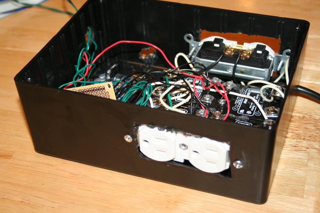
Now here you have a couple options. If you are confident of our wiring skills you can do like I did and take a couple of sockets and hook up the neutral and ground in parallel. Two save space and since I really didn’t need two separate plug-ins (nor its own plug) for each relay I removed the little metal bar between the two sockets so they could be switched on independently. Now simply hook up hot to the left side of all your relays in parallel and then connect a wire from the right side of the relay to its own plug on the two sockets.
Now a less wiring intensive method is to simply take a 6 foot (small if you can find them) and cut the hot wire (usually the one with non-smooth wire) and attach each end of the wire to both sides of the relay.
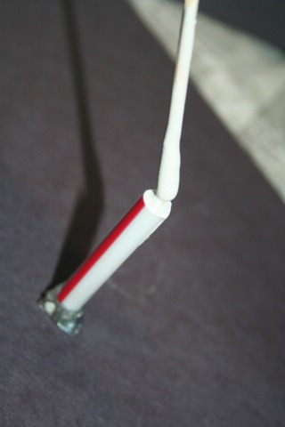
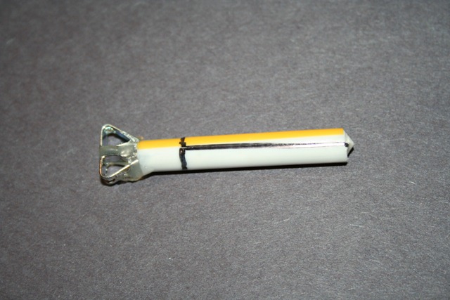
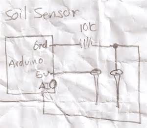
Moisture Sensor
When it comes to a moisture sensor there are a few options. First is the classic two galvanized nails, second is the cheap gypsum soil moisture sensor which I have written up in the provided link.
If you are using the other options you will need the simple circuit below. Technically it is a voltage divider, but that doesn’t really matter. Just hook up one end of your sensor to 5V and other sensor to ground with 10K resistor and also connected to analog pin 0.
My custom PCB solution

I actually started the work to create my own PCB at least a few years back. Played with if it off and on and finally pulled the trigger to get some boards printed up which I must say was very rewarding and pretty fun experience for just $20-30 of out of pocket cost. This provides all the circuits I mention above with a bonus circuit to let me know when my water reservoir is running low. I also installed a Ethernet socket not
I designed this to be an Ardunio which plugs directly on top of the Arduino. In theory I could stack more functionality on top of if but haven’t though of anything cool to do here yet.
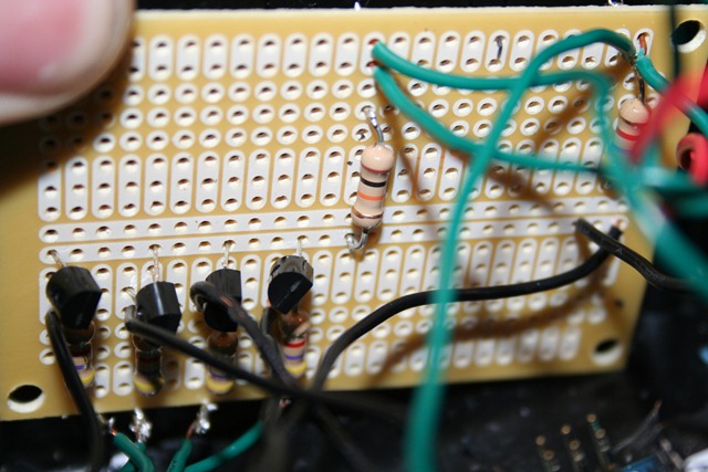
Don’t want to spend 10-20 hours creating your own PCB and then wait 2-3 weeks for it to arrive from Hong Kong? Well you can do the same thing with a bread board which I show below.
Virtual breadboard layout
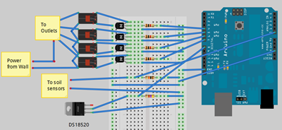
If you are new to soldering or have no interest in learning I would definitely recommend this option. Simply place the components in the holes and make connections with 18 gauge solid copper wire. You should be able to pick a small breadboard for less than $7.
Various applications
Of course for my application, I am using this to integrate with my custom software solution to control my grow box. Specifically soil sensor, temperature measurement, heater, lights, exhaust fan, and water pump. So using the circuit mentioned above I ran the hot wire through each SSR with the remaining wires connected to the plug and eventually gets plugged into the wall. Then simply hooked up the wire from the Ethernet cables to the low voltage side to turn the switches on/off. So I would say this is a bit of an improvement over my last attempt…
Before
After

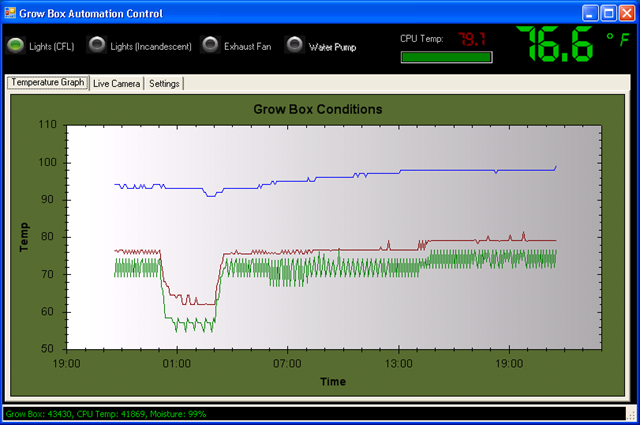
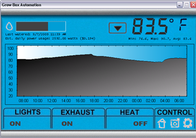
Last I hooked the arduino up to my PC and used my custom software to control the temperature, water, and provide cool graphs as you can see below.
Sometimes life can get busy and you have limited time to keep an eye on your plants, for these times I also integrated with a custom Windows Phone 8 application which allows me to check the current state of the grow box using life tiles, water remotely (turn on/off lights/heater/fan as well), or even check out a current feed inside the grow box.


Looks at the actual actual grow box…