Computer controlled grow box – Part 1
15.3 years ago cheap, computer, electronics, indoor growbox, PC thermometer
The Idea and Design
My PC Grow box was very effective though it did have some shortcomings along with my desire for tinkering caused me to create a new version code named “Project Everbearing” after the test subjects for the project, several Everbearing strawberry plants I propagated from my garden last Summer/Fall. The specific shortcomings I wanted to overcome were temperature control and limited size. My grow box has to live in my garage so on cold nights the temperatures can fall low enough to kill my summer seedlings (tomatoes/cucumbers) Size is an easy fix just make it bigger though it is more difficult to keep a larger grow box warm and still well lit.�
My solution to both of these problems was the addition of a computer to the system. First computers generate heat, using this along with computer controlled fans and incandescent lights (heater) allow me to regulate the heat to my desired levels. This is the point a normal person may have just stopped, but I am far from normal and decided a few more features, which I will explain more below.


The Structure and Insulation
First comes the structure, upon inheriting a set of shelves from my sister, we ran out of room for some of our existing storage shelves (see above), though we used the buckets to store loose toys on our new shelves we had the structure of the old one sitting in the garage for some time. After many passes by in the garage not knowing what do do with this shell, it finally came to me that this would be perfect for my new grow box, (Reduce/Reuse/Recycle) in action. The only customization required was the removal of a couple of the wooden dowels and I was ready to add some hardware. Of course you could do the same thing with an old bookshelf, cabinet or just with construct your own frame with a 12”X1”X8’ foot board cut in two along with two 1”X1”X8’ pieces of lumber cut into two. Screw one 1”X1” in each corner and should should have a pretty solid frame. For the top I used pegboard mainly because I bought a 4’ by 8’ sheet when I only needed half of it but worked really good to use zip-ties to secure various components and provides decent airflow between the computer and growing areas.
Second comes insulation, after some not so careful calculations and measurements I determined I could cover the 3 exposed areas with 2 sheets of 2’ by 4’ sheets of insulating Styrofoam. I glued and taped (duct tape of course) the Styrofoam which was cut using a utility knife and straightedge to cut to size making sure I made the top straight and flush. I then created an exactly copy of the other side and one more piece for the top. Using a long strip of duct tape I created a hinge for the top and glued side of the box. The last piece I simply fit into place using a tool box to ensure a tight fit but also allows easy access to plants when needed.
The Lighting
I went cheap on the lighting taking from the success of the PC grow box I decided to go with a similar setup using $2.00 home depot wired sockets hooked up to an couple old computer power cords. I went with two 24 watt CFL bulbs and one incandescent bulb. Though the incandescent is not as efficient and the CLFs it does provide a full spectrum of light and a little extra heat which the box can use in the many times cold garage where it lives. The CFLs and incandescent exist on two separate circuits so they can be controlled independently by the software.
The Software — Grow box brains
Now I know all of this could be done with a Basic Stamp or Arduino pretty easy, but I wanted the ability to track history and have a decent user interface to look at, so I wrote a windows form application using C#. To cover the basic functionality of temperature control I used the parallel port outputs hooked up to the computer’s parallel port to give the software the ability to turn the lights on and off. By configuring a “sunset” and “sunrise” time which I am in complete control over the lights will turn on and off as appropriate. I added some logic to ensure the plants stay at a comfortable temperature (thresholds configurable) by turning on the incandescent bulb when it is too cold and an exhaust fan when it gets too hot. In order to allow the computer to know these temperatures I used a PS2 controller to create two temperature sensors one for the area the plants are growing and another for the top area where the CPU resides (computer was too old to have onboard temperature sensor)
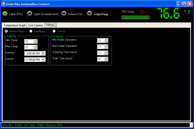
My daughter thought it would be cool if we have some sort of automatic watering system. I agreed, so I added a moisture sensor and created an algorithm to periodically check the moisture level and activate a water pump to add water until it reaches the specified moisture level. I still need to buy and hookup the pump but coding portion is complete and tested.
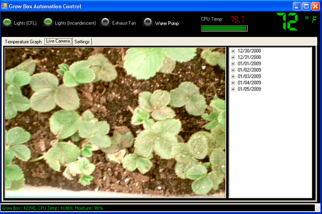
I live in the Pacific Northwest it rains a lot and can get cold in the evenings and I don’t want to trek out to check on my plants. solved this by adding the computer to my Wi-Fi network now I can take look at them by connecting to the machine wirelessly and see how they are doing through it’s webcam. I also take periodic pictures of the plants so I can create cool time-lapse videos of progress like the one below. I also have the ability to browse through pictures taken at specific time periods.
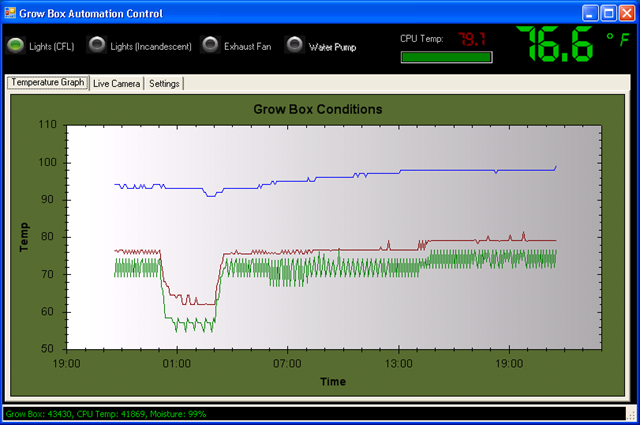
Finally to store all of this data I installed SQL Server 2005 Express (free) which allows me to track historical data of the conditions and images over time. If you have data, you definitely need some graphs. Being too lazy to do this graphic work I leveraged ZedGraph (free) to allow some visual tracking of temperatures and moisture content.
Features for future versions (Beta 2?)
- Finish automated watering
- Add automated red LED lights for flowering stage
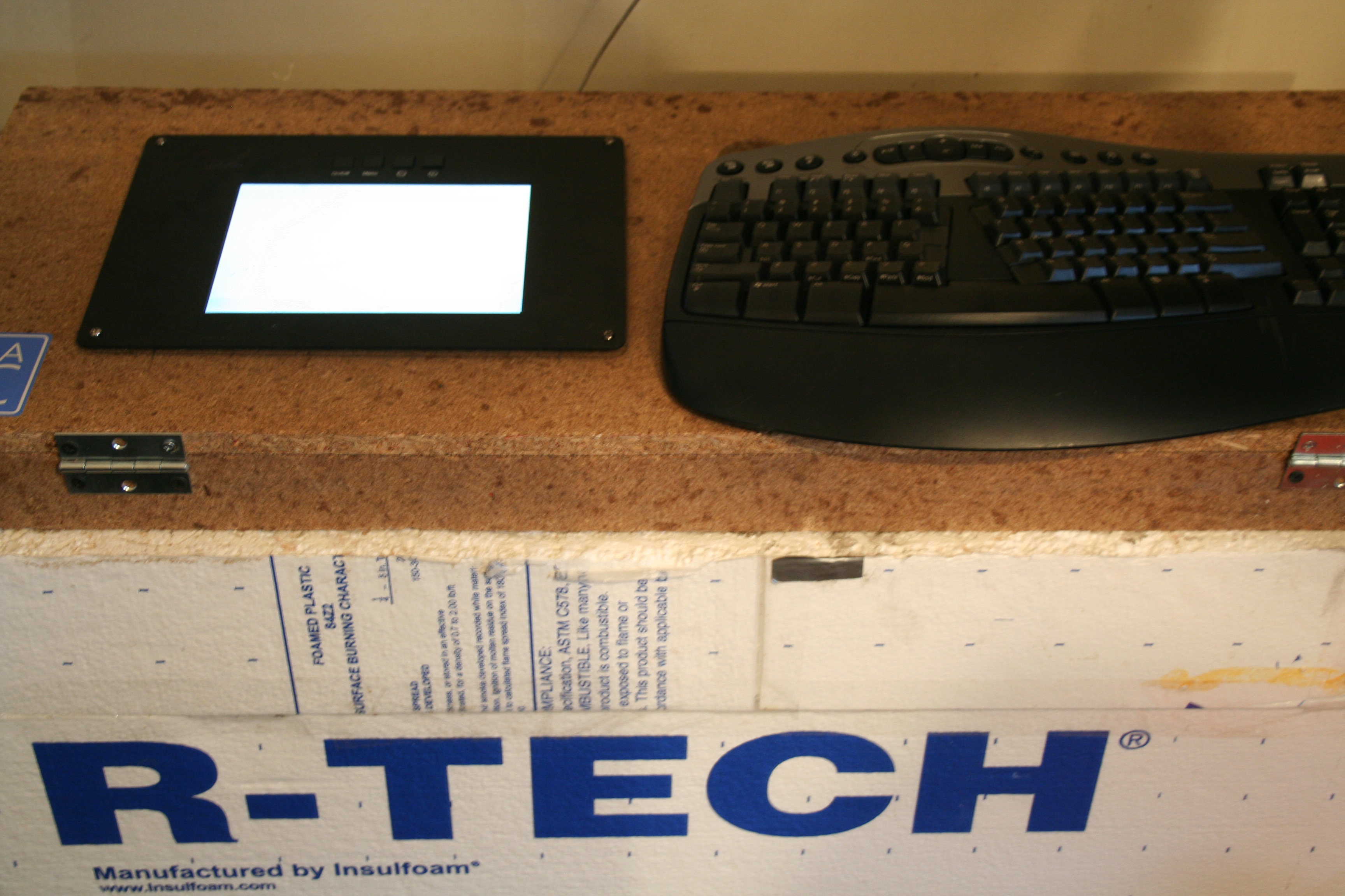
- Install LCD Panel
- Make box look better (real door which does not require tape to open/close)
- Create single USB controller for lights/sensors
- Better/additional camera
Video of grow box “booting” up, personally I like the flashing lights when the computer sends signal through the parrallel port. If you are old enough to ever have a printer that used a parallel port this is when it would make its annoying sound letting you know it was alive.
Updates:
Computerized Grow Box Update #1
Tags: arduino, cheap, garden seeds, grow lights, growbox, led, outdoor plants, strawberry plants, tomato plants, vegetables
Create a cheap PC thermometer with PS2/Gamepad Controller
15.4 years ago cheap, electronics, PC thermometer

You might be thinking what does this post have to do with vegetable gardening? Bear with me, I don’t have time to do a complete write up on it right now but let’s just say this is a component for “Project Everbearing” I gave my 7-year-old the honors of coming up with the codename, since he is my faithful assistant and cheerleader.
For my current project I need the ability to measure temperature with my PC. Now there are plenty of gadgets out there I could have simply purchased a commercial product for around $40+ and saved myself a lot of time but I really wanted to brush some dust off my soldering iron and try to save some cash, this is the CHEAP vegetable gardener after all.
After a little searching online seemed like a good place to start was to pick up a few thermoresistors which is a special type of resistor which increases resistance as the temperature increases. With no luck at my local RadioShack I picked up a few on EBay for less than $1 a piece.
Now comes the hard part of actually using them, since the computer I was using was old enough it still have an old 15-pin game port I went that route first. This would have been my easiest method of implementation by simply connecting the resistor to pin 1 and pin 3, since analog joysticks work with variable resistance as well. They use what is called a potentiometer which as the user moved the stick to left/right it raises/lowers the resistance. If this would have worked all that I would have needed to do is get the measurement and start calibration. Unfortinately this port was no longer responsive so I have to go with another option

Fortunately I never throw anything electrical out and pulled an old PS2 controller with an USB adapter out of my junk box. Knowing that the analog controllers also work with potentiometers, I found my victim. After removing the screws in the back I started warming up the old soldering iron to completely void the long gone warrantee on the controller. Now all I needed to do was attach two wires connected to the thermoresistors, solder the wires to the point connected to the potentiometer and that is pretty much did it. Given there are two sticks with X and Y axises for both you could have up to 4 temperature sensors (I chose to go with 2) The controller did does have one feature where it automatically turns off the analog control after no use for a couple minutes. After thinking about some more complicated solutions, I went low tech by forcing the L2 button to the on position by applying a piece of electrical tape over it.
I won’t go into the gritty details of the software to actually get the numbers from the joystick since M Harris has already done that so well on his CodeProject writeup.
Last comes calibration, when I purchased the thermoresistors they also included detailed specifications on the tested resistance values at various temperatures, which with a little bit of physics and some fun math, in theory I could have avoided the whole calibration but given the length of wire and/or my sloppy soldering could skew the accuracy of the temperatures I opted for a more manual approach. I put my “thermometer” in a plastic bag along with my trusty $5 digital thermometer and dropped it in an ice cold water bath, while recording the temperature changes as the temperature increased to room temperature. I followed this by doing the same with hot water bath until it lowered to room temperature, recording values as the temperature decreased.
With this data I entered it into Microsoft Excel and got a nice graph (see below) which gave my nice magic formula of:
Temperature = 0.0059(joystick X Axis position) – 138.57

By simply doing the math I now can capture values on my PC.
Tags: cheap, led, vegetables


