Wet Circuits water resistant power strip review
13.3 years ago electronics, power strip, product review, water, waterproof, wet circuits
One problem with growing plants indoors is the requirement for indoor lighting, combined with the need to pour water on plants around such lighting causes a potential electrical disaster. When I heard about Wet Circuits water/tamper resistant power strip I simply had to try it out. Not having the $70 to buy one myself, the nice people at WetCircuits sent me a sample to try out these claims for myself.
After reviewing their very informative infomercial style demonstration (see below) I felt I would not be doing my job unless I reproduced at least some of these demonstrations for myself.
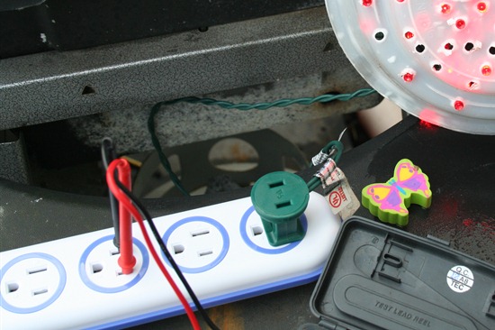
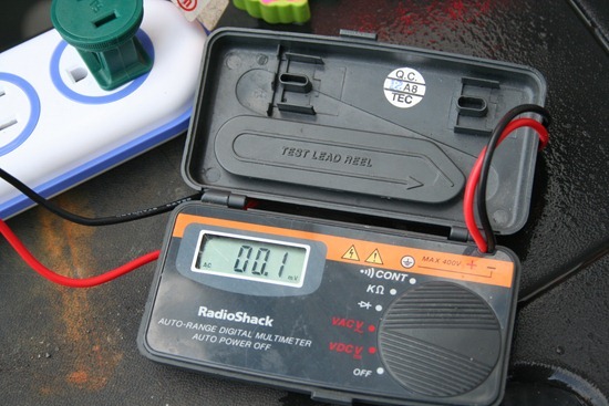
Being cautious I started with sticking in my voltmeter while having my homemade supplemental LED light plugged in.
Test #1 one passes with flying colors
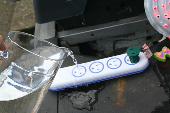
Next it was time to pour water on the live outlet…now using a normal socket this would result in a nice spark if you were lucky. As you can see from the video below, this also passed without any problems.
I decided to skip the tweezers test provided that the voltmeter answered the expected result and well it is just plain scary to try even when I know it won’t shock me.
Now if you have shelves of grow lights or your own grow box for $70 this is a decent investment though it does buy you some piece of mind.
Homemade waterproof digital thermometer
14.3 years ago arduino, electronics, thermometer, Uncategorized, waterproof
Now I am playing with hydroponics in my grow box I want to monitor the temperature of my nutrient tank. This is important too hot it can bread disease too cold it can shock your plants. I also want to use the data to identify how ebb/flow cycles affect ambient and solution temperature (for my own nerd curiosity)
I have been thoroughly impressed with the Dallas DS18S20 temperature sensor so decided this would be a great component to use for this project and this is how you can make your own.
Materials:
- DS18S20 temperature sensor
- 1/2 inch plastic tubing (could go smaller but had some lying around)
- Aquarium/food grade silicone
- 18 gauge solid core wire (long enough to get from arduino to what you want to measure)
- Glue gun with glue
- Soldering iron with solder
Construction
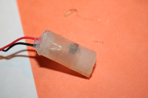
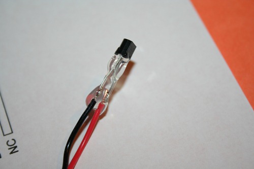
Step 1: Solder the two wires to pins 1 and 2 of the DS18S20 and apply a little dab of hot glue to all of the exposed metal. This is not entirely necessary but a small safety precaution so you don’t discover you shorted the connection during assembly.
Step 2: Cut approximately 1 inch length of plastic tubing using a utility knife
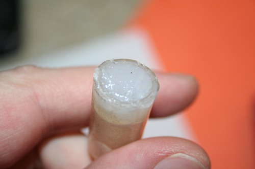
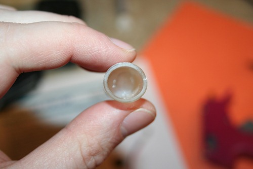
Step 3: Apply liberal amount of silicone to one end of the tubing cut in step 2.
Step 4: Allow silicone to set for 15 minutes and do a visual inspection for leaks. You may also try blowing very gently into the tube to check for leaks, though not too hard to create a hole in the process.
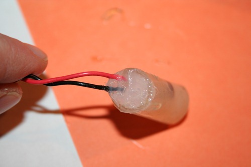
Step 5: Attach the DS18S20 to the tube using a drop of hot glue. This is not entirely necessary but when trying to get a perfect watertight seal the less moving parts the better.
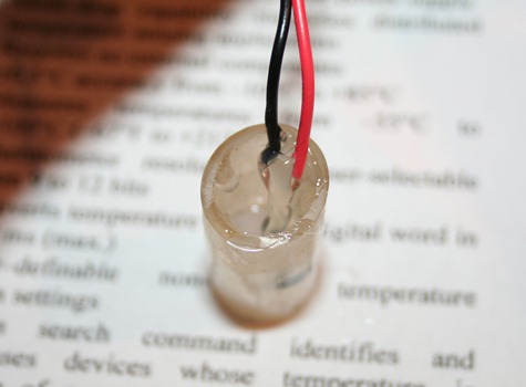
Step 6: Again apply a liberal amount of silicone to seal the top paying special attention to the area around the wires
Step 7: Give the silicone at least 24 hours to completely set.
Step 8: Testing. First off the sensor may be buoyant, if this is the case carefully attach a 1/2 hose clamp or something else to help tether it down. Next suspend in a glass of water (preferably clear) and watch for a few minutes for leaks and or bubbles. If you see bubbles try to get an much water as you can out and apply a more silicone and let set for another 24 hours
Hooking it up
This part is pretty straightforward. Pin 1 is your ground and pin 2 is your DQ which for most people doesn’t make much sense but it is a combination power source and bus output. To get this to work you hook up your ground (black wire) to your ground on your arduino and the red wire to digital in and 5v with 4.7K resistor between. Sure that is very confusing so hopefully the breadboard visual below is much more helpful.
Writing the Code
Since I am planning on using this with my grow box controller, I will show how to use this with arduino to get some numbers. You could look at my arduino code in the grow box controller post to get the values but in my case I need to get values from two DS18S20 temperature sensors so I found a great OneWire library which helps make your arduino code very simply. Simple extract the two folders in the zip archive to [ArduinoPath]\hardware\libraries and enter the following code into the arduino UI:
#include <OneWire.h> #include <DallasTemperature.h>
OneWire oneWire(8); // on pin 8 DallasTemperature sensors(&oneWire);

void setup()
{
  Serial.begin(9600);
  // Initialize sensors
  sensors.begin();
}

void loop()
{
    sensors.requestTemperatures();
    Serial.print(“Sensor #0: “);
    Serial.println(sensors.getTempCByIndex(0));

    Serial.print(“Sensor #1: “);
    Serial.println(sensors.getTempCByIndex(1))

    delay(100);  // wait a little time
}
If all goes well you should see output similar to the following (values in Celsius):
 Sensor #0: 20.3
 Sensor #1: 30.4
 Sensor #0: 20.3
 Sensor #1: 30.4
 Sensor #0: 20.3
 Sensor #1: 30.4
For people like me who are used to Fahrenheit you can simply use the following equation to convert Celsius to Fahrenheit:
°F = °C x 9/5 + 32
Though I am using this for my grow box controller there are many other uses you could use this for:
- Aquarium temperature monitoring
- Brewing temperature monitoring
- Weather station
- Soil thermometer
Tags: arduino, cheap, growbox, outdoor plants, vegetables
