Growing Pepper Plants Indoors
13.9 years ago Bhut Jolokia, indoor growbox, jalapeno, peppers
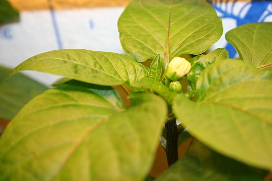
Pepper plants need specific environmental (temperature and humidity) conditions to establish growth and create high yields. If the temperatures get too low it will stunt its growth or not produce blossoms, when the temperatures get too high the plant will drop it blossoms resulting in no or reduce yields.
The perfect temperature range for peppers is between 70 and 80 degrees F for Bell peppers and hot peppers can handle a little warmer temperatures up to 85 degrees. If their environment gets below 70 degrees the plants will struggle, which given even in August we don’t hit an average of 70 degrees F for any success a greenhouse, hot box, or a growbox is requirement. If you are a frequent reader of this site you probably already know I go with the last option.
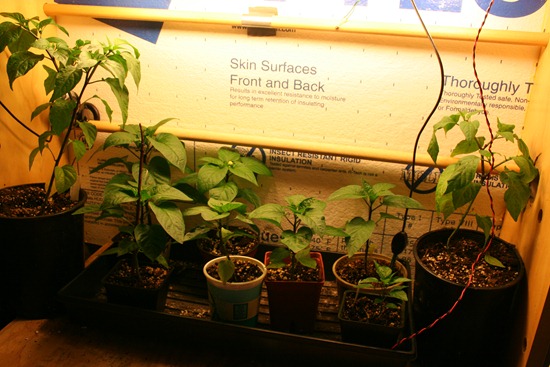
With a few CFLs (or incandescent if extra heat is needed) the peppers plants are happy in the growbox. With exception of once a week watering with a diluted fertilizer at 50% recommended on the box they pretty much take care of themselves. If we do get a nice warm day I will bring them out for some natural light. This also invites some natural organic pest control of any aphids which may have found their way into the growbox. When the plants begin flowering this also gives some bees an opportunity to do a little pollination, this can be done by hand with a paint brush or Q-Tip though my success rate is much less than the bees, though they have been doing this for millions of years…I am still a little new at this
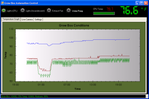
As mentioned above controlling the proper temperature is critical, I do this with a combination of computer controlled fans and lighting to maintain the proper temperature, though this could also be achieved by using a $10 outdoor digital thermometer and a occasional adjustments to venting or fan control to maintain a good temperature range.
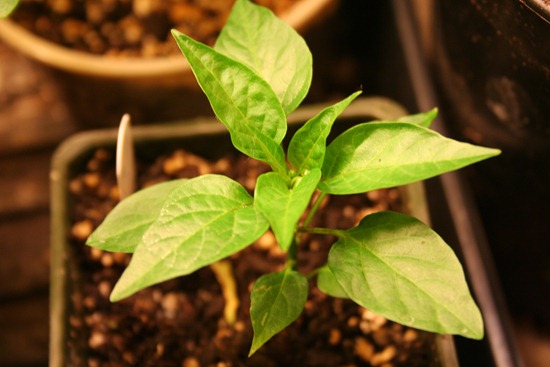
Last year I only grew jalapeno pepper plants, but this year I am also trying Cayenne, Sweet Yellow, and Bhut Jolokia pepper plants. Though it is quite a bit more work growing peppers in my area, I like challenges and to do things that others say can not be done, call me stubborn.
Tags: growbox
Earth Day in the garden
14 years ago cilantro, cold season crops, garlic bulbs, onions, peppers, tomato
I decided to take the day off to catch up on some things at home and as I ended up outside of course I went right to the garden.
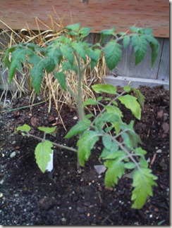
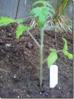
We have seen a few warm days here in the Northwest and in my area we haven’t dipped under 40 degrees at night so seemed like a good time to plant a few of my tomatoes spending their time this winter in the grow box.
Above are a New Yorker and Persey both of which are new for me this year. They have been growing great even with my neglect during their youth. I also have some Green Zebras, Husky Cherry, Sweetie Cherry, and Yellow Cherry. I did attempt Red Brandywine but the seeds I got appear to be duds.
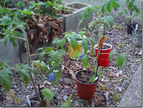
Given it is always good to have a Plan B so I have twins of these tomato plants still in puts which I can bring if a cold snap comes and kills off the plants I ambitiously planted in the ground.
Elsewhere in the garden I have some herbs: Parsley and Oregano, with Basil being an unfortunately casualty which I will plan on buying from the store and try again next year.
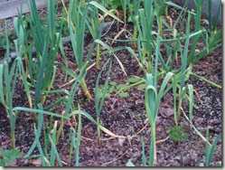
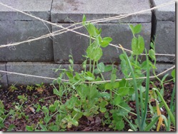
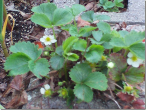
Next I checked out my larger garden bed to see my peas, cilantro, onions, carrots, lettuce, strawberries and garlic
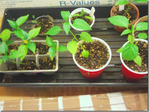
Lastly I checked out the peppers in the grow box which they will stay until we have some warmer nights (at least 50 degrees) otherwise can cause significant stunting of growth. So until then they will remain happy in the grow box and given they are still pretty small, still plenty of room to grow…
Tags: cheap, cilantro, garden seeds, garlic bulbs, growbox, herb garden, outdoor plants, pepper plants, strawberry plants, tomato plants, vegetables
Life in the growbox
14.1 years ago indoor growbox, peppers, tomato
Right about now the temperatures outside should be increasing and I should be thinking about start hardening off my summer plants over the next few weeks.
Unfortunately we seeing hail the past few days along with some pretty cold nights. Looks like even though I was fairly pessimistic about my last frost date I may have another battle of tomatoes/peppers over taking the growbox or bring them out into the elements a little too early…
To make a little room I did move my herbs (oregano/parsley) out to the cold frame with the basil struggling to survive in the growbox I will give it a little time to bounce back.
Tags: cheap, growbox, herb garden, outdoor plants, pepper plants, tomato plants, vegetables
Hydroponic Grow box update
14.2 years ago Uncategorized
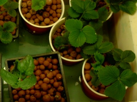
Currently in the grow box I have some basil and more recently strawberries added as I was “weeding” my garden I found a bunch more starts. Though I have seen basil do well in hydroponic systems mine is turning pretty leggy and quickly loosing lower leaves. The strawberries on the other hand and thriving in the environment. Probably will let them stay in there a little longer until the peppers get too big and make me move the hydroponic system outdoors.
I also tried some peppers but unfortunately they got a little too much of a freeze from a previous machine failure and didn’t quite make it.
For those who can’t get enough of time lapse videos here is some interesting growth going on in the grow box.
Tags: cheap, growbox, pepper plants, strawberry plants, vegetables
How to make a grow box controller (Original)
14.2 years ago arduino, cheap, LEDs, vegetables
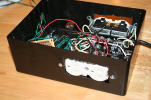
While my existing system was working I decided to make an upgrade to the electronics on my old system for several reasons:
- I needed to add more automated external controls (heater, fans, water pump) with my existing design this was entirely possible though was starting to get a little clunky.
- The existing controller (PS2 Controller, parallel port with various wires to control relays) worked but was not exactly compact.
- Wanted a modular design so if I needed to debug some issue I could simply unplug the USB and power and bring it out of the box in the garage for needed work
- Ability for others to create so I can share my software without forcing people to hack PS2 controllers to get to work
- Ability to use components like 1Wire temperature sensors (others to come) and Arduino
- Just for the fun of it
Well now I have attempted to justify my reasons this is what I used to put the whole thing together:
Parts List
- Black plastic project case (8”X6”X3”)
- Breadboard or multipurpose PC board
- soldering iron and solder (optional if using breadboard)
- Arduino
- 4 – solid state relays
- 4 — 1K resistor
- 4 — 2N2222 transistor
- 4 — 1N4004 diode
- DS18S20 (1Wire temperature sensor)
- 4.7K resistor
- (10K resistor and homemade soil sensor) or Vegetronix soil sensor
- 20 gauge solid copper wire (recommend multiple colors)
- Heavy duty extension cord
- 2 — outlet sockets
- 2 — socket faceplate (optional)
- hot glue gun and glue
If we had lawyers, they probably would want us to say this:
WARNING: I am not an electrician and do not pretend to be one. I do not know the specific building electrical codes of your area, so please be sure your wiring is completed under the proper safety code for your area. As always, using high voltage electricity can result in self-electrocution or burn down your house if not done safely so if you are not comfortable doing this wiring please contact a qualified professional.
Putting it all together
On the electronics side overall the circuits are actually pretty simple and if using a breadboard definitely something that could be tackled by a beginner. Though on the other side since this project is dealing with AC current I definitely would recommend caution (no hands unless power is unplugged) or have someone a little more comfortable with 120/220V help you out.
The Brains
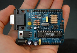
I will be the first to admit that using an Arduino for this application is complete overkill for this application but it gives plenty of room for additions in the future. For all intensive purposes you could have your grow box completely controlled from the Arduino own processing power though on my case the software and UI is more interesting part to me. For this reason the Arduino code is actually very “dumb” basically just taking commands via the build in serial through USB and setting digital outputs to HIGH/LOW or reading analog inputs.
Here is the code for your grow box controller:
1: /*
2: * GrowBox Arduino Interface
3: *
4: * Descriptions: Simple interface to digital and analog controls by passing serial inputs
5: * For example:
6: * "A1" to read analog value on pin 1
7: * "D1H" to set digital pin 1 to HIGH
8: */
9: #include <OneWire.h>
10:
11: //1-wire
12: OneWire ds(8); // on pin 8
13: #define BADTEMP -1000
14:
15: //define unique sensor serial code
16: byte temperature[8];
17:
19: #define PIN_VALUE 1 // numeric pin value (0 through 9) for digital output or analog input
18: #define ACTION_TYPE 0 // 'D' for digtal write, 'A' for analog read
20: #define DIGITAL_SET_VALUE 2 // Value to write (only used for digital, ignored for analog)
21:
22: int NUM_OF_ANALOG_READS = 2;
23: char commandString[20];
24:
25: void setup()
26: {
27: Serial.begin(9600);
28:
29: setOneWireHex();
30:
31: // Power control
32: for(int i=0; i<=7; i++)
33: {
34: pinMode(i, OUTPUT); // sets the digital pins as output
35: digitalWrite(i, LOW); // turn everything off
36: }
37: }
38:
39: void loop()
40: {
41: readStringFromSerial();
42:
43: if (commandString[ACTION_TYPE] != 0) {
44: int pinValue = commandString[PIN_VALUE] - '0'; // Convert char to int
45:
46: if(commandString[ACTION_TYPE] == 'A')
47: Serial.println(analogRead(pinValue));
48: else if(commandString[ACTION_TYPE] == 'D') {
49: if(commandString[DIGITAL_SET_VALUE] == 'H')
50: digitalWrite(pinValue, HIGH);
51: else if(commandString[DIGITAL_SET_VALUE] == 'L')
52: digitalWrite(pinValue, LOW);
53:
54: Serial.println("OK");
55: }
56: else if(commandString[ACTION_TYPE] == 'T') {
57: float temp = get_temp(temperature);
58:
59: Serial.print(temp);
60: Serial.println("C");
61: }
62: else if(commandString[ACTION_TYPE] == '1') {
63: printOneWireHex();
64: }
65: else if(commandString[ACTION_TYPE] == 'V') {
66: Serial.println("VERSION_1_0_0_0");
67: }
68: else if(commandString[ACTION_TYPE] == 'P') {
69: Serial.println("PONG");
70: }
71:
72: // Clean Array
73: for (int i=0; i <= 20; i++)
74: commandString[i]=0;
75: }
76:
77: delay(100); // wait a little time
78: }
79:
80:
81: void readStringFromSerial() {
82: int i = 0;
83: if(Serial.available()) {
84: while (Serial.available()) {
85: commandString[i] = Serial.read();
86: i++;
87: }
88: }
89: }
90:
91: void setOneWireHex() {
92: ds.reset_search();
93: ds.search(temperature);
94: }
95:
96: void printOneWireHex() {
97: ds.reset_search();
98: if ( !ds.search(temperature)) {
99: Serial.print("NONE\n");
100: }
101: else {
102: ds.reset_search();
103:
104: int sensor = 0;
105: while(ds.search(temperature))
106: {
107: Serial.print("S");
108: Serial.print(sensor);
109: Serial.print("=");
110: for(int i = 0; i < 8; i++) {
111: Serial.print(temperature[i], HEX);
112: Serial.print(".");
113: }
114: Serial.println();
115: }
116: }
117:
118: ds.reset_search();
119: }
120:
121: float get_temp(byte* addr)
122: {
123: byte present = 0;
124: byte i;
125: byte data[12];
126:
127: ds.reset();
128: ds.select(addr);
129: ds.write(0x44,1); // start conversion, with parasite power on at the end
130:
131: delay(1000); // maybe 750ms is enough, maybe not
132: // we might do a ds.depower() here, but the reset will take care of it.
133:
134: present = ds.reset();
135: ds.select(addr);
136: ds.write(0xBE); // Read Scratchpad
137:
138: for ( i = 0; i < 9; i++) { // we need 9 bytes
139: data[i] = ds.read();
140: }
141:
142: int temp;
143: float ftemp;
144: temp = data[0]; // load all 8 bits of the LSB
145:
146: if (data[1] > 0x80){ // sign bit set, temp is negative
147: temp = !temp + 1; //two's complement adjustment
148: temp = temp * -1; //flip value negative.
149: }
150:
151: //get hi-rez data
152: int cpc;
153: int cr = data[6];
154: cpc = data[7];
155:
156: if (cpc == 0)
157: return BADTEMP;
158:
159: temp = temp >> 1; // Truncate by dropping bit zero for hi-rez forumua
160: ftemp = temp - (float)0.25 + (cpc - cr)/(float)cpc;
161: //end hi-rez data
162: // ftemp = ((ftemp * 9) / 5.0) + 32; //C -> F
163:
164: return ftemp;
165: }
Copy and paste the above code into your Arduino software. For the code above I used the OneHire.h library which is free to use and can be downloaded from here. To be able to use this library simply copy the contents to C:\arduino\hardware\libraries\OneWire. Now you should be able to Compile (CTRL+R) and upload the code to the board (CTRL+U)
Now with the software uploaded you can send some simple serial commands via its built in USB to serial adapter to interact with it. The interface is are broken up into 1 to 4 character commands, which I will detail below
| Command | Description |
| T | Returns temperature from One Wire component |
| D4H | Sets digital pin 4 to HIGH (ON) (replace 4 for alternate pin) |
| D4L | Sets digital pin 4 to LOW (OFF) (replace 4 for alternate pin) |
| A1 | Reads analog value from pin 1 (replace 1 for alternate pin) |
| PING | Returns PONG which is used to confirmed controller is online |
| V | Returns version which is some forethought into the PC application being able to support different versions of controller software |
Using the build in serial monitor tool in Arduino.exe, my application, or you should be able to control your Arduino with this very simple command based interface
Now you can hook up some LEDs and watch them blink which is fun for a little while but if you want to add some grow box components read on….
Temperature Sensor
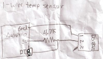
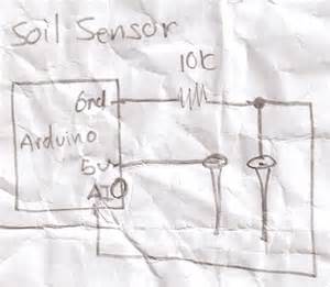
As you can see I have fully embraced the circuit schema on the back of a napkin idea. These are the actual diagrams I crumpled up and stuffed in my pocket with several trips to the garage for some final soldering of various joints until everything was solid.
Below is the simple circuit required to get your 1Wire temperature sensor working. I would recommend checking your documentation (if not labels on the chip) for the orientation to have 1 and 3 correct, if you have it wrong you should get some complete unrealistic number. Hook ground up to pin1 on the DS18S20 and pin 2 hooked up to the digital input pin 8 on the Arduino with 5V with a 4.7K resister in between to step down the voltage.
If everything is hooked up correctly you should get the current room temperature in Celsius by sending command “T” to your Arduino. If you prefer Fahrenheit uncomment line 162 and recompile and upload your changes, though if using my software I support both degree types and do the conversion in the the software. To make sure everything working (or just to play with your new toy) put your fingers on the chip for a couple seconds and take another measurement unless you keep your house very warm the temperature should go up a couple of degrees
Turning things on and off (Relays)
If you were smart enough to check the current requirements of your Solid State Relays (SSR) before you bought them you may be able to skip this whole circuit and simply hook the digital outputs to the 5V positive side and ground to the negative side of the SSR.
Unfortunately if you are like me and bought some SSRs that require more current draw than the Arduino (or any other IC chip) of 40mA then you will need to create the simple circuit below.
Basic idea is pretty simple, you are using the output from the digital pins to switch of the transistor which then allows the ground to complete the circuit with the thus turning on the relay. As you can see there is a 1K resistor between the base (middle pin) of the transistor. If you are not using a SSR relay (though recommend you do) you should add a 1N4004 diode between the positive/negative which protects the transistor from being damaged in case of a high voltage spike which can occur for a fraction of a second when the transistor switched off, this is also known as a back-EMF diode or fly back diode.
Now here you have a couple options. If you are confident of our wiring skills you can do like I did and take a couple of sockets and hook up the neutral and ground in parallel. Two save space and since I really didn’t need two separate plug-ins (nor its own plug) for each relay I removed the little metal bar between the two sockets so they could be switched on independently. Now simply hook up hot to the left side of all your relays in parallel and then connect a wire from the right side of the relay to its own plug on the two sockets.
Now a less wiring intensive method is to simply take a 6 foot (small if you can find them) and cut the hot wire (usually the one with non-smooth wire) and attach each end of the wire to both sides of the relay.
Moisture Sensor
When it comes to a moisture sensor there are a few options. First is the classic two galvanized nails, second is the cheap gypsum soil moisture sensor which I have written up in the provided link. Lastly if my personal favorite the Vegetronix soil sensor.
If you use the Vegetronix hookup is simple no circuit needed simply hook up the 5V to red, bare wire to ground, and black to analog pin 1.
If you are using the other options you will need the simple circuit below. Technically it is a voltage divider, but that doesn’t really matter. Just hook up one end of your sensor to 5V and other sensor to ground with 10K resistor and also connected to analog pin 0.
Cheap soldered solution
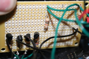
If I could do it over I probably should have just bought a small breadboard. I did most of my prototyping with my larger breadboard but got cheap when I was at Radio Shack The Shack and just got this prototype board for half the price.
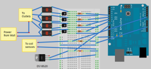
Virtual breadboard layout
If you are new to soldering or have no interest in learning I would definitely recommend this option. Simply place the components in the holes and make connections with 18 gauge solid copper wire. You should be able to pick a small breadboard for less than $7.
Various applications
Of course for my application, I am using this to integrate with my custom software solution to control my grow box (will be having private/public beta soon). Specifically soil sensor, temperature measurement, heater, lights, exhaust fan, and water pump.
Though there is definitely no reason you can use this same setup for other application.
A couple of ideas:
- Home automation (turn on/off lights, turn on coffee machine)
- Attic fan
- Hydroponic system
Going Forward
I would like to convert this into an Arduino shield. For those new to Arduino I will go with Arduino’s description, “Shields are boards to be mounted on top of the Arduino board and that extend the functionality of Arduino to control different devices, acquire data, etc”
So basic idea is you just plug it into the top the Arduino and hook up a couple wires to some terminal blocks and you have a nice clean solution. Creating these printed circuit boards get much cheaper the higher the quantity. I am considering doing a run of these if I get enough interest so if you may be interested in one of these send me a mail in “Contact” in the header.
Tags: arduino, cheap, coffee grounds, grow lights, growbox, led, vegetables
LED grow box gets an upgrade
14.2 years ago cheap, indoor growbox, indoor seed starting, LEDs, seeds
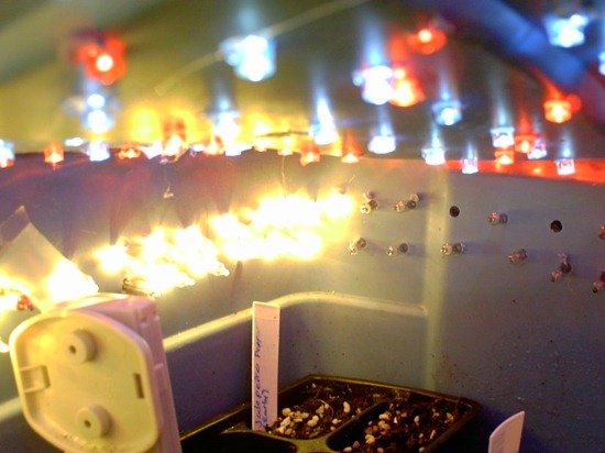
In our family we are not just cheap in the garden we also keep our house pretty cool to save on heating costs. Unfortunately since the LEDs in my grow box do not put out very much heat the inside is only about 68 F degrees even placing it on top of my refrigerator. For most seeds 77 F degrees is a great ball bark number to shoot for to get the best germination percentage as well as quicker germination times. This was the number I was shooting for, so I decided to add a string of mini incandescent bulbs to help bring up the temperature.
To do this I did exactly what I did for the LEDs just drill a hundred or so holes into the side of the box just slightly smaller than the bulb. Then had the fun job of pushing them all through.
I first tried having all the lights on but that brought the temperature up to 85 degrees, next I tried only half the lights on…70 F degrees. Then I got the idea of adding the blinker bulbs and tada 77 F degrees on the nose (ok technically 77.1 F).
So far everything is looking good have some onions, peppers, basil, and Swiss chard already sprouted and expecting more shortly.
Tags: cheap, garden seeds, grow lights, growbox, led, pepper plants, vegetables
